BRIDGEMILL MODS
Tailstock

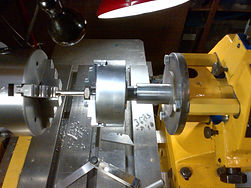
The tailstock is designed to sit back as far as possible to accommodate long work, however in order to use it for close up work I made the mode below.

By bringing part of the assembly out front and using these spacers, I am now 4 inches closer to the chuck, and can reach over the table easier.

Now it's close enough to use without extensions, which reduces flex and increases accuracy. Also cuts down on setup time.

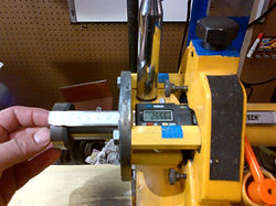
Addition of a micrometer to the tailstock for depth when using for boring or drilling
Motors

Motor to raise and lower the bridgemill section. Old computer reel to reel tape system motor, gears from my old Honda 125, and window switch from a 1983 Audi.


X axis drive motor. Old motor from a daisy wheel printer. (Not sure what that is? Look it up) They need to be high torque to jump between letters with quick pauses and starts.

Newly made timing gear

Timming gear just cut. Just neads sides pressed on

Stock bar turned down to size for timing gear

Y axis drive motor. Also a motor from a daisy wheel printer.

Spec drawing.

Z axis spindle pulley shown, normally connected to main spindle pulley limiting up/down to a non-variable speed. Here now shown with a small DC motor connected to variable speed drive from an Razor electric scooter. Now drilling can start real slow, move to medium speed, and than fast to retract.
Example
Mill Spindle Stop
3 Pictures

Position originally designed for changing belts


I added this pin to hold the belt system in disengaged position. It allows for quick stops to adjust boring head, changing bits without stopping motor

Position originally designed for changing belts
Mill Belt Disengagement, I added in a spring engaged pin. This pin pops up to lock the pulley system back disengaging belts while the motor is running, and just push down to reengage. Big help when repeatedly changing boring head circumference setting, or drill bits. Not shown hear is a rubber friction stop that sits on a spring swivel mount that puts friction on middle pulley when in disengaged position to prevent any slight friction from belts in moving the spindle.
TOOL POST

I added this 360 degree scale to the tool post so I knew what angles I was working with. Made the ring and the Index plate. Printed scale on Inkjet

With magnifying glass added.

On the zero mark.

On the half degree.

Gear Cover
New stiffer side plate. I added a grease fitting for front and back bearings so the machine doesn't need to dissembled to lube it. To match the paint, I ended up mixing my own spray paint from yellow, bit of red and a tad of cyan. Email me if you want details.

New thicker plate, also changed from a flat gasket to an O-ring style seal to allow metal to metal contact to reduce bridgemill arm flex. (Full seal was installed after picture) I added in a oil fill window.

Opening for gear accessis a fairly large, so in analyzing machine vibrations and core flex, I felt a new plate would help

Scrap about to become new plate
Support Beam

New I beam to replace the Bridge-mill end support to reduce vibration.

New I beam ready to go

Beam in place
Way Covers

Way cover made from old honeycomb blinds

Second row is cut in to at a 60 degree angle to hook under the way keeping it riding in place. There are also plastic guides every 5 folds for enhanced hold down.